The structural analysis software RFEM 6 is the basis of a modular software system. The main program RFEM 6 is used to define structures, materials, and loads of planar and spatial structural systems consisting of plates, walls, shells, and members. The program also allows you to create combined structures as well as to model solid and contact elements.
RSTAB 9 is a powerful analysis and design software for 3D beam, frame, or truss structure calculations, reflecting the current state of the art and helping structural engineers meet requirements in modern civil engineering.
Do you often spend too long calculating cross-sections? Dlubal Software and the RSECTION stand-alone program facilitate your work by determining section properties of various cross-sections and performing a subsequent stress analysis.
Do you always know where the wind is blowing from? From the direction of innovation, of course! With RWIND 2, you have a program at your side that uses a digital wind tunnel for the numerical simulation of wind flows. The program simulates these flows around any building geometry and determines the wind loads on the surfaces.
Are you looking for an overview of snow load zones, wind zones, and seismic zones? Then you are in the right place. Use the Geo-Zone Tool to determine quickly and efficiently snow loads, wind speeds, and seismic data according to ASCE 7‑16 and other international standards.
Would you like to try out the capabilities of the Dlubal Software programs? You have the opportunity to do so! The free 90-day full version allows you to thoroughly test all our programs.
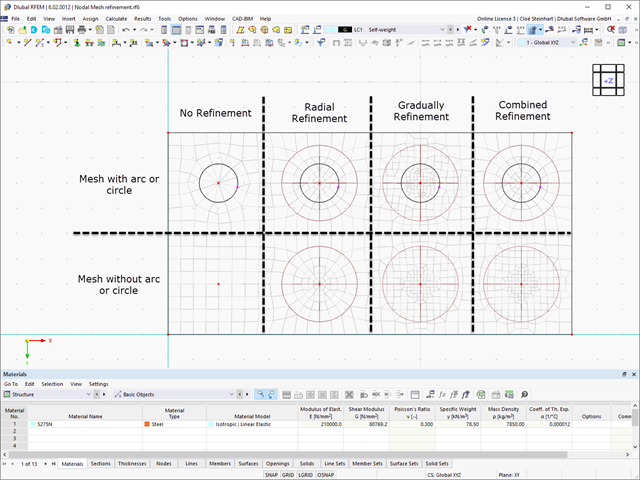
A nodal mesh refinement allows you to generally control the generation of an FE mesh to achieve an adapted discretization achieved in the refinement area around a node.
You can select between two types of the mesh refinement that are available for the geometric shape of the refinement area:
For the circular type, it is necessary to define the size of the circular compression area via a radius on the one hand, and the inner and the outer target length on the other hand. The outer FE length usually corresponds to the global mesh size.
In the case of a rectangular type, the "Side Length" of the cube-shaped compression area as well as the "Inner Target FE Length" are specified.
For circular refinements, you can use the "FE length arrangement" to control how the mesh size of the FE mesh expands from the inside to the outside. For this, a distinction is made between the following options:
Modal massEach multi-mass system can usually be represented by a single-mass system. When performing this transformation, the modal mass of the system is necessary. This mass is required to generate the frequency of the equivalent single-mass oscillator.
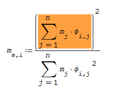
Participation factorThis factor can also be negative because it consists of the equivalent mass on a node and the corresponding displacement due to the mode shape. If the deflection is in the negative direction, the participation factor becomes negative. However, the equivalent mass factor is still positive because the participation factor is squared (see the formula).
Equivalent massThe equivalent mass of a structural system is a part of the total mass that is excited due to the vibration of the multi-mass oscillator. The equivalent mass of a structural system can be between zero and the total mass. The equivalent mass factor is only the quotient from the total mass to the equivalent mass. Thus, it is usually possible to check the ratio of the excited mode mass of the respective mode shape more quickly. If the equivalent mass factor is greater than 1, you should check the discretization of the system and, if necessary, refine the division of the nodes or the FE mesh.
Generally, the equivalent mass factor and the equivalent mass are decisive for an earthquake analysis, because these values are used to calculate the dynamic equivalent loads on the building.
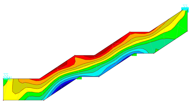
The display of the FE mesh quality can help you calculate planar structural components. When generating the mesh, the created FE elements are subjected to an internal check according to specific criteria. The result can be displayed graphically. Three quality levels are displayed: in green, yellow, or red.
The values of the checked criteria can be customized. Thus, you can adjust them to your individual requirements.
Checking the FE mesh quality thus allows an evaluation of the discretization. For example, it is possible to localize areas that require FE mesh refinement. However, it cannot replace the check of the FE mesh by the engineer.